Authored by:
Christian R. Falyar, DNAP, CRNA
Director of the Acute Surgical Pain Management Fellowship
Assistant Professor
Duke University School of Nurse Anesthesia

Sound Basics
- Sound is a pressure wave that is created when a vibrating object (stereo) sets a medium (air) in motion. The vibrations create a variation in density causing the medium to vibrate back and forth
- Longitudinal waves, such as sound, travel (aka propagates) parallel the direction of movement. This is different from a transverse wave, such as water, where the variations in pressure move up and down (perpendicular) as it propagates
- Mechanical waves require a medium (air, water, tissue, etc.) to propagate. Sound cannot travel in a vacuum, such as space
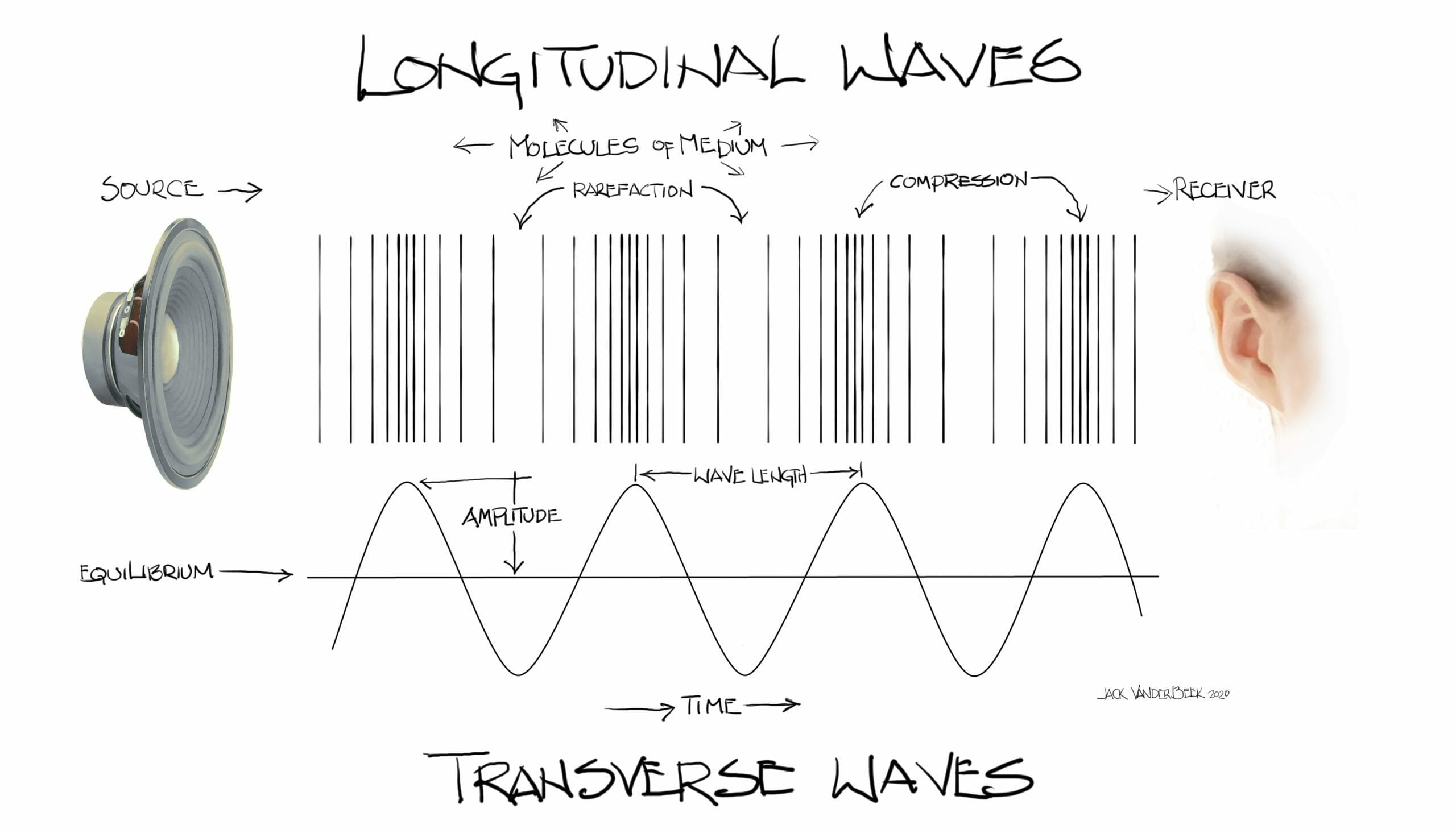
Figure 1: Sound is a traveling variation of pressure. Vibrations created by the stereo causes the displacement of molecules in the medium (in this case air).
Click to view full image
Wave Terminology
- Sound is described using the following terms: frequency, period, wavelength propagation speed, amplitude and intensity
-
-
- Frequency – Frequency (f ) is the number of times something happens. As sound travels, variations in pressure result in areas of high pressure (compressions) and low pressure (rarefactions). When these variations are combined, it forms a complete cycle. The number of cycles that occur in a second is measured in Hertz (Hz)
-
![]()
-
-
- Humans can hear sound frequencies from 20 Hz to 20,000 Hz. Sound frequencies greater than 20,000 Hz is called ultrasound. In diagnostic ultrasound, frequency impacts the resolution and penetration of images (See Figure 2)
-
- High frequency ultrasound, greater than 7 million cycles/sec, or megahertz (MHz), creates high resolution images, but with poor penetration
- Low frequency ultrasound, typically 1-5 MHz, has lower resolution images but with greater tissue penetration
-
- Humans can hear sound frequencies from 20 Hz to 20,000 Hz. Sound frequencies greater than 20,000 Hz is called ultrasound. In diagnostic ultrasound, frequency impacts the resolution and penetration of images (See Figure 2)
-

-
- Period – Period is the time it takes for one cycle to occur. The greater the frequency, the smaller the period. The common unit for period is microsecond, where one microsecond equals 0.000001 second. This is an important concept in pulsed-wave ultrasound used in diagnostic imaging
- Wavelength – Wavelength is the physical distance from the beginning to the end of one cycle and is measured in millimeters (mm). The higher the frequency, the shorter the wavelength. Image resolution is dependent on wavelength
- Propagation velocity – Propagation velocity (c) is the speed at which a wave moves through a medium. Velocities are measured in meters per second (m/s) and millimeters per microseconds (mm/us). The physical properties of the medium (density and stiffness) determine c, and all waves, regardless of f, travel through a specific medium at the same speed
-
- Propagation speeds are lower in gases (air), higher in liquids, and highest in solids (bone)
- In diagnostic imaging, all tissue is assigned the same c, 1540 m/s, known as the “soft tissue average”
-
- Wavelength is dependent on frequency and propagation velocity. The relationship is defined by the following equation:
![]()

Image Creation
- Pulsed Ultrasound – The terms frequency, period, wavelength and propagation velocity are used to describe a continuous wave of sound where cycles repeat infinitely. In diagnostic imaging and Doppler ultrasound, pulsed-ultrasound is used to create an image in which short, pulsed waves are sent into the tissue followed by gaps of periods of no sound

-
- Pulse-Repetition Frequency – Pulse repetition frequency (PRF) is specific to pulsed-wave ultrasound (diagnostic imaging and Doppler), and describes the number of pulses generated every second. PRF is automatically controlled by the ultrasound system and is important as it determines how many images are created.
-
- A PRF of 5,000 Hz, or 5 kilohertz (kHz) means that 5,000 pulses are generated each second
- A typical linear array transducer will have approximately 100 piezoelectric crystals aligned along the face of the transducer. Each crystal emits a scan line; collectively they form a “sheet” of energy called a sound beam
-
- If it takes 100 scan lines to create an image and the PRF is 5 kHz, up to 50 images per second are created. This is known as the frame rate. Since the frame rate of the ultrasound exceeds that of the human eye, the image appears to be moving in real-time
-
-
- Pulse-Repetition Frequency – Pulse repetition frequency (PRF) is specific to pulsed-wave ultrasound (diagnostic imaging and Doppler), and describes the number of pulses generated every second. PRF is automatically controlled by the ultrasound system and is important as it determines how many images are created.

Attenuation
- Attenuation is the weakening of a sound wave as it propagates through a medium. Amplitude and intensity describe how strong an ultrasound wave is, and impacts attenuation
-
- Amplitude – the amount of variation in the high and low pressure variables in a wave. For example, a large wave in the ocean has a much higher amplitude than the ripple wave created when throwing a rock into a pond. The peak and trough of the waves are further from its undisturbed state
- Intensity – describes the speed at which power passes through area. Power describes the transfer of energy from one place to another. Work cannot be done without energy. Sound is mechanical energy that does work.
- Attenuation encompasses absorption, reflection and scattering of sound when it interacts with tissues. In general attenuation is bone > soft tissue (lung > other soft tissue)
-
- Absorption is the conversion of sound to heat
- Reflection and scattering create echoes seen in imaging
-
-


Figure 4: Attenuation is the degradation of a sound wave its interaction with sound. In the image on the left, attenuation is seen in the far field (FF) limiting the assessment of anatomic structures during this adductor canal block. When the provider increases the gain in the FF, it creates a uniform image, and the provider can now identify and avoid both the blood vessels when performing the block.
Echoes
- Ultrasound is useful because of the echoes (reflections) created at organ and tissue interfaces. The reflective waves produce a pattern of echoes that create an image. Two types of echoes to consider are perpendicular and oblique
-
- Perpendicular reflection describes an echo that travels returns in the direction of the incident (originating) wave. This is commonly associated with specular reflection, when sound reflects of a large smooth surface (bone)
-
- Impedance determines how much of a sound wave is reflected back into the first medium and how much passes into the second medium (see Table 2)
-
- Impedance increases with density and propagation velocity
-
- Impedance determines how much of a sound wave is reflected back into the first medium and how much passes into the second medium (see Table 2)
-
- Perpendicular reflection describes an echo that travels returns in the direction of the incident (originating) wave. This is commonly associated with specular reflection, when sound reflects of a large smooth surface (bone)
-
![]()
-
-
- Refraction occurs when the direction of transmitted wave (any type) changes at the boundaries of two tissues from the incident wave
-
- Refraction can cause distorted views (think of a fishbowl)
- No refraction will occur if the propagation speeds of both tissues are the same
-
- Scattering is the redirection of reflections in multiple directions that occurs when a wave contacts tissue boundaries with rough surfaces, also known as diffuse reflection
-
- Raleigh scattering
-
- Refraction occurs when the direction of transmitted wave (any type) changes at the boundaries of two tissues from the incident wave
-

Doppler Ultrasound
- Doppler ultrasound is used to detect motion. It cannot create an image. Doppler has many everyday used, such as sonar on ships and radar speed detection. While it is not used to create an image, it has many uses in diagnostic imaging. A few important points regarding Doppler:
-
- The Doppler signal is dependent on the cosine of the insonation angle
-
- At an angle of 0 degrees (or 180 degrees) the object is directly in-line with the signal and the full Doppler effect is obtained
- At an angle of 90 degrees, the object is perpendicular to the signal and no Doppler effect is generated
- In diagnostic imaging, the optimal Doppler angle is 60 degrees or less
-
- For the Doppler effect to occur, either the sender or receive must be moving, otherwise no Doppler shift will occur
- The Doppler signal is dependent on the cosine of the insonation angle
-

- Ultrasound systems use the colors red and blue to depict positive and negative Doppler shifts. These colors are often depicted as arterial and venous blood flow
-
-
- The operator determines which color represents a positive or negative shift; this is often based on the anatomic area being scanned
-
-
- When performing regional procedures, Doppler is useful in detecting aberrant vasculature structures near target nerves

Transducers
Image Resolution
-
- Resolution is the smallest distance between two points where the can still be discriminated
-
- Axial resolution is the ability to differentiate two separate objects in-line with the axis of the ultrasound beam
-
- High frequency transducers have better axial resolution
-
- Lateral resolution is the ability to identify two different objects side-by-side
-
- Determined by the number of crystals along the transducer face
-
- Axial resolution is the ability to differentiate two separate objects in-line with the axis of the ultrasound beam
-
- Resolution is the smallest distance between two points where the can still be discriminated
-
- Ultrasound Beam Zones
-
- The natural tendency of an ultrasound beam is to converge before diverging as the beam attenuates. An ultrasound beam can be divided into the near, focal and far zones
-
- The Fresnel Zone, or near field describes the sound beam as it leaves the transducer and the waves converge.
-
- Image resolution is good in this zone
-
- The focal zone is the point where the beam is the narrowest
-
- Resolution is best in the focal zone
-
- The Fraunhofer Zone, or far field is the area distal to the focal zone. As the beam attenuates, it weakens and diverges creating potential gaps in the beam
-
- Image resolution is poor here
-
- The Fresnel Zone, or near field describes the sound beam as it leaves the transducer and the waves converge.
-
- The natural tendency of an ultrasound beam is to converge before diverging as the beam attenuates. An ultrasound beam can be divided into the near, focal and far zones
-
- Ultrasound Beam Zones
